


A Component diagram illustrates the pieces of software, embedded controllers and such that make up a system, and their organization and dependencies . A Component diagram has a higher level of abstraction than a Class diagram; usually a component is implemented by one or more Classes (or Objects) at runtime. They are building blocks, built up so that eventually a component can encompass a large portion of a system.
Example Diagram
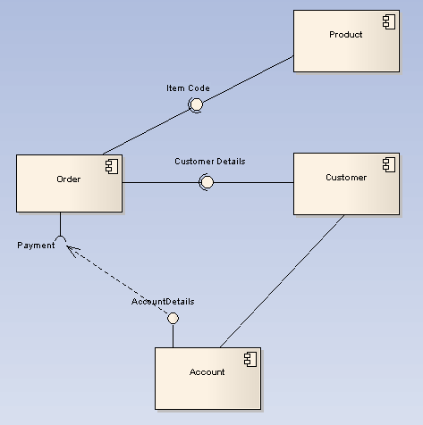
The diagram below demonstrates some components and their inter-relationships. Assembly connectors link the provided interfaces supplied by Product and Customer to the required interfaces specified by Order. A Dependency relationship maps a customer's associated account details to the required interface Payment, indicated by Order.
Toolbox Elements and Connectors
Select Component diagram elements and connectors from the Component pages of the Enterprise Architect UML Toolbox.
Tip: Click on the elements and connectors below for more information.
Component Diagram Elements |
Component Diagram Connectors |
|
|
|
|
|
|
|
|
|
|
|
|
|
|
|
|
|
|