


A Custom diagram is an extended Class diagram that is used to capture requirements, user interfaces or custom-design models.
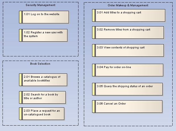
The below example reflects a Requirements diagram. Requirement elements can be linked back to Use Cases and Components in the system to illustrate how a particular system requirement is met.
Screen design is supported through a stereotyped Screen element and UI Controls. Use this model to design high level system prototypes.
Custom models provide a few extensions to the UML model and enable some exploratory and non-rigorous experimentation with model elements and diagrams.
Toolbox Elements and Connectors
Select Custom diagram elements and connectors from the Custom pages of the Enterprise Architect UML Toolbox.
Tip: Click on the elements and connectors below for more information.
Custom Diagram Elements |
Custom Diagram Connectors |
|
|
|
|
|
|
|
|
|
|
|
|
|
|