Enterprise Architect provides the facility to layout diagrams automatically. This creates a tree-based structure from the diagram elements and relationships in a diagram. Owing to the complexity of many diagrams, you might then have to do some manual 'tweaking'.
Note: This facility is available for Structural diagrams and Extended diagrams, but not for Behavioral diagrams (see UML diagrams for a description of the diagram types).
Layout a Diagram
To layout a diagram, follow the steps below:
| · | The Diagram | Layout Diagram option, or |
| · | The Auto Layout button on the diagram toolbar . |
Note: Dynamic and Analysis diagrams are NOT suited to this form of layout - please ensure first that the diagram type you are laying out benefits from the action.
Accessing the Diagram Layout Options Dialog
For a fine degree of control of the elements in your diagram, you can use the Diagram Layout Options dialog. Generally the default layout parameters provide adequate layouts for a wide range of diagrams, but there are times when more specific settings are required. To access the Diagram Layout Options dialog, follow the steps below:
| 1. | Double-click on the background of the diagram to display the Diagram Properties dialog. |
| 2. | Click on the Diagram tab, then click on the Set Layout Style button. The Diagram Layout Options dialog displays. |
| 3. | When you have made the required changes, click on the OK button to save the changes. |
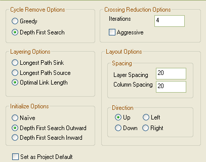
You can alter any of the following settings on the Diagram Layout Options dialog to refine your layout:
| · | Cycle Remove Options panel - these settings determine the type of cycle removal to be used during layout: |
| · | Greedy - Select to use the Greedy Cycle Removal algorithm. |
| · | Depth First Search - Select to use the Depth First Search Cycle Removal algorithm. |
| · | Layering Options panel - these settings determine the type of layering to be used during layout. |
| · | Longest Path Sink - Select to use the Longest Path Sink Layering algorithm. |
| · | Longest Path Source - Select to use the Longest Path Source Layering algorithm. |
| · | Optimal Link Length - Select to use the Optimal Link Length Layering algorithm. |
| · | Initialize Options panel - these settings determine the type of initialization of indices and columns to be used during layout. |
| · | Naive - Select to use the Naive Initialize Indices algorithm. |
| · | Depth First Search Outward - Select to use the Depth First Out Initialize Indices algorithm. |
| · | Depth First Search Inward - Select to use the Depth First In Initialize Indices algorithm. |
| · | Crossing Reduction Options panel |
| · | Iterations - Type the number of iterations to be used during cycle removal. |
| · | Aggressive - This option enables you to specify whether or not to use an aggressive (time-consuming) crossing reduction step. |
| · | Select to use the aggressive crossing reduction |
| · | Deselect to not use the aggressive crossing reduction. |
| · | Layer Spacing - Type the default number of logical units between layers. |
| · | Column Spacing - Type the default number of logical units between columns. |
| · | Up, Down, Left, Right - Select the direction in which directed links should point. |
| · | Set as Project Default checkbox |
| · | Select this checkbox to apply the diagram layout settings to all diagrams in the project. If you later check this box and click on the OK button for a different diagram, the new settings override the settings saved earlier. |
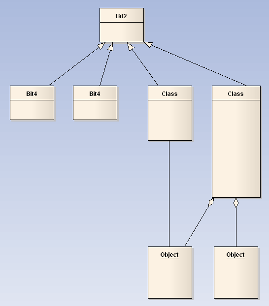
The following is an example of an automatically laid out diagram: