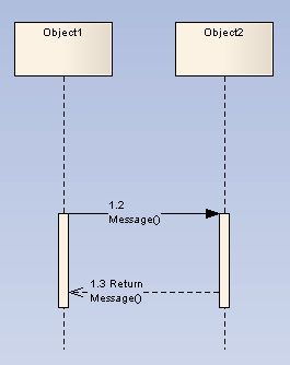
Sequence diagrams depict work flow or activity over time using Messages passed from element to element. These Messages correspond in the software model to Class operations and behavior. They are semantically similar to the Messages passed between elements in a Communication diagram.
To create a Message on a Sequence diagram, follow the steps below:
| 1. | Access the Sequence diagram. The Interaction pages of the Enterprise Architect UML Toolbox display. |
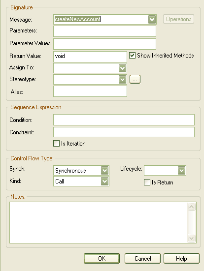
| 2. | In the Interaction Relationships page, click on the icon, click on the source object and drag the cursor to the destination (target) object. The Message Properties dialog displays (if not, right-click on the Message and select the menu option).
|
| 3. | In the field, type the Message name. |
Note: If the Message flow is towards a Class element (dropped in from a Class diagram) or a Lifeline element having a classifier, and the destination Class has defined operations, you can click on the drop-down arrow and select an appropriate operation name. The Message reflects the destination Class operations.
Similarly, if the Message flow is from a Class element or Lifeline element with classifier, and the source Class has defined attributes, you can click on the drop-down arrow and select an appropriate attribute name. The Message reflects the attributes from the source Class.
| 4. | In the field, type any parameters that the Message has, as a comma-separated list. If required, in the field type the actual value for each parameter, again as a comma-separated list. |
| 5. | If the Message is a return message, in the field enter the returned value or type. |
Note: It is possible to depict returns from a Self Message. Simply create a second Self Message at the end of execution and select the checkbox in the Control Flow Type panel.
| 6. | In the field, type or select an optional stereotype for the link (this is displayed on the diagram, if entered). |
| 7. | If required, in the field type an alias for the name of the Message. |
Note: On the diagram, the alias displays if the checkbox is selected on the Diagram tab of the Diagram Properties dialog. The Alias displays instead of or as well as the Message name, depending on the setting selected in the Alias Usage panel of the Diagram Behavior page of the Options dialog.
| 8. | In the field, type any conditions that must be true in order for the message to be sent. |
| 9. | In the : field in the Control Flow Type panel, select or as appropriate. |
| 10. | In the field, select to create a new element at the end of the Message, or to terminate the message flow at the end of the Message. If neither case applies, leave the field at the default of <none>. |
| 11. | Click on the button to save the Message definition. |
Co-Region Notation
Co-Region notation can be used as a short hand for parallel combined fragments. To access the Co-Region submenu, right-click on a connector in a Sequence diagram and select the menu option. There are four sub-options available:
Toolbox Icon

See Also


