Sequence diagrams are one of two types of UML interaction diagrams (we'll explore the second type, collaboration diagrams, a bit later in this chapter). Sequence diagrams are a way of graphically portraying how messages should flow from one object to another in carrying out a given scenario.
We'll illustrate the process of creating a sequence diagram by creating one for Scenario #1 of the "Register for a Course" use case, which was presented in Chapter 9.
To prepare a sequence diagram, we must first determine
Which classes of objects (from among those that we specified in our static model [class diagram] in Chapter 10) are involved in carrying out a particular scenario
Which external actors are involved
Looking back at Scenario #1 for the "Register for a Course" use case, we determine that the following objects are involved:
One Student object (representing Fred)
One Section object (representing the course titled "Beginning Objects," course number OBJ101, section number 1)
One PlanOfStudy object, belonging to Fred
One Transcript object, also belonging to Fred
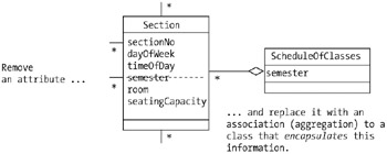
The scenario also mentions that the student "views the schedule of classes for the current semester to determine which section(s) he wishes to register for." You may recall that when we were determining what our candidate classes should be back in Chapter 10, we debated whether or not to add ScheduleOfClasses as a candidate class to our model, and elected to leave it out at that time. In order to fully represent the details of Scenario #1, we're going to reverse that decision, and retrofit ScheduleOfClasses into our UML class diagram now as follows:
We'll show ScheduleOfClasses participating in a one-to-many aggregation with the Section class because one ScheduleOfClasses object will be instantiated per semester to represent all of the sections that are being taught that semester. (It's an abstraction of the paper booklet or online schedule that students look at in choosing which classes they wish to register for in a given semester.)
We'll also transfer the semester attribute from the Section class to ScheduleOfClasses. Since each Section object will now be maintaining a handle on its associated ScheduleOfClasses object by virtue of the aggregation relationship between them, a Section object will be able to request semester information whenever it is needed.
The results of these changes to our class diagram are highlighted in Figure 11-7.
Acknowledging ScheduleOfClasses as a class in our model allows us to now reference a ScheduleOfClasses object in our sequence diagram, as we'll see in a moment. Scenarios often unearth new classes, attributes, and relationships, thus contributing to our structural "picture" of the system; this is a common occurrence, and is a desirable side effect of dynamic modeling.
Of course, we must remember to add a definition of ScheduleOfClasses to our data dictionary!
| Note?/td> |
Schedule of Classes: A list of all classes/ sections that are being offered for a particular semester; students review the schedule of classes to determine which sections they wish to register for. |
Finally, since the scenario explicitly mentions interactions between the student user and the system, we'll reflect Fred the actor separately from Fred the object. Doing so will allow us to represent the SRS interacting externally with the user, as well as showing the system's internal object-to-object interactions. We refer to an object that represents an abstraction of an actor as an instance of a boundary class.
Our adjusted list of object/actor participants is now as follows:
One Student object (representing Fred)
One Section object (representing the course titled "Beginning Objects," course number OBJ101, section number 1)
One PlanOfStudy object, belonging to Fred
One Transcript object, also belonging to Fred
One ScheduleOfClasses object
One Student actor (Fred again!)
To prepare a sequence diagram for Scenario #1, we do the following:
We draw vertical dashed lines, one per object or actor that participates in the scenario; these are referred to as the objects' lifelines. Note that the objects/ actors can be listed in any order from left to right in a diagram, although it's common practice to place the external user/actor at the far left.
At the top of each lifeline, as appropriate, we place either an instance icon—that is, a box containing the (optional) name and class of an object participant—or a stick figure symbol to designate an actor. (For rules governing how an instance icon is to be formed, please refer back to the section on creating object diagrams in Chapter 10.)
Then, for each event called out by our scenario, we reflect its corresponding message as a horizontal solid-line arrow drawn from the lifeline of the sender to the lifeline of the receiver.
Responses back from messages (in other words, return values from methods, or simple return; statements in the case of methods declared to have a void return type) are shown as horizontal dashed-line arrows drawn from the lifeline of the receiver of the original message back to the lifeline for the sender of the message.
Message arrows appear in chronological order from top to bottom in the diagram.
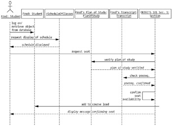
The completed sequence diagram for Scenario #1 is shown in Figure 11-8.
| Note?/td> |
Note that we've intentionally omitted one element of sequence diagram notation from this example: namely, the use of focus of control bars to illustrate the period of time over an object's lifeline that the object is actually engaged in processing a request. For more details on sequence diagram notation, please see the recommended reading suggestions in Chapter 17. |
Let's step through the diagram to make sure that we understand all of the activities that are reflected in the diagram.
When Fred logs on to the system, his "alter ego" as an object is activated (see Figure 11-9).
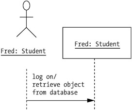
Figure 11-9: hen Fred logs on, a Student object is created.
| Note?/td> |
Presumably, information representing each Student—in other words, the Student object's attribute values—is maintained offline in persistent storage, such as a DBMS or file, until such time as he or she logs on, at which time the information is used to instantiate a Student object in memory, mirroring the user who has just logged on.We'll talk about reconstituting objects from persistent storage in Chapter 15. |
When Fred the user/actor requests that the semester class schedule be displayed, we reflect the message "request display of schedule" being sent to an anonymous ScheduleOfClasses object. The dashed-line-arrow response from the ScheduleOfClasses object indicates that the schedule is being displayed to the user, strictly speaking, via a GUI (see Figure 11-10).
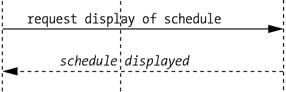
Figure 11-10: As requested, a schedule of classes is displayed.
| Note?/td> |
We've chosen to label our response arrows with italic instead of regular font, a slight departure from official UML notation. |
The next message shown in our diagram is a message from the user to the Section object, requesting a seat in the class.
| Note?/td> |
This message is shown originating from the user; in reality, it originates from a graphical user interface (GUI) component object of the SRS GUI, but we aren't worrying about such implementation details at this stage in the analysis effort.We'll talk about the object-oriented aspects of graphical user interface design and event processing in depth in Chapter 16. |
Note that there is no immediate reply to this message; that's because the Section object has a few other objects that it needs to consult with before it can grant a seat to this student, namely
The Section sends a message to the object representing Fred's plan of study, asking that object to confirm that the course that Fred has requested is one of the courses required of Fred in completing his degree program.
The Section next sends a message to the object representing Fred's transcript, asking that object to confirm that a prerequisite course— say COMP 001—has been satisfactorily completed by this student.
Assuming that both of these other objects respond favorably, as they are expected to do by virtue of how this scenario was written, the Section object then performs some internal processing to verify that there is indeed room for Fred in this section. We reflect internal processing within a single object as an arrow that loops back to the same lifeline that it starts with, as shown in Figure 11-11.
Figure 11-11: Availability of the requested section is confirmed.
Of course, if we were to reflect all of the internal processing that is performed by every one of the objects in our sequence diagram, it would be flooded with such loops! The only reason that we've chosen to show this particular loop is because it's explicitly called out as a step in Scenario #1; if we had omitted it from our diagram, it might appear that we had accidentally overlooked this step.
Finally, with all checks having been satisfied, the Section object has two remaining responsibilities:
First, it sends a new message to the "Fred" Student object, requesting that the Student object add this Section to Fred's course load.
Next, the Section object sends a response back to Fred the user/actor (via the GUI) confirming his seat in the section. This is the response to the original "request seat" message that was sent by the user toward the beginning of the scenario! All of the extra "behind the scenes" processing necessary to fulfill the request—involving a Section object collaborating with a PlanOfStudy object, a Transcript object, and a Student object—is transparent to the user. As we saw earlier in the chapter, Fred merely selected a section from the schedule of classes that was displayed on the SRS GUI, clicked the Add button, and, a few moments later, saw a confirmation message appear on his screen.
Of course, as with all modeling, this particular sequence diagram isn't necessarily the best, or only, way to portray the selected scenario. And, for that matter, one can argue the relative merits of one scenario as compared with another. It's important to keep in mind that preparing sequence diagrams is but a means to an end: namely, discovering the dynamic aspects of the system to be built—that is, the methods—to complement our static/structural knowledge of the system. Recall that our ultimate goal for Part Two of the book is to produce an object-oriented blueprint that we can use as the basis for coding the SRS as a C# application in Part Three. But, as we've already pointed out, the class diagram that we created in Chapter 10 had a noticeable deficiency: all of its classes' operations compartments were empty. Fortunately, sequence diagrams provide us with the missing pieces of information.