


A Communication diagram shows the interactions between elements at run-time in much the same manner as a Sequence diagram. However, Communication diagrams are used to visualize inter-object relationships, while Sequence diagrams are more effective at visualizing processing over time.
Communication diagrams employ ordered, labeled associations to illustrate processing. Numbering is important to indicate the order and nesting of processing. A numbering scheme could be:
1
1.1
1.1.1
1.1.2
1.2, and so on.
A new number segment begins for a new layer of processing, and would be equivalent to a method invocation.
Example Diagram
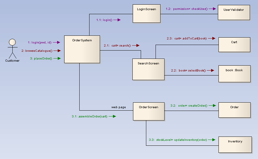
The example below illustrates a Communication diagram among cooperating object instances. Note the use of message levels to capture related flows.
Toolbox Elements and Connectors
Select Communication diagram elements and connectors from the Communication pages of the Enterprise Architect UML Toolbox.
Tip: Click on the elements and connectors below for more information.
Communication Diagram Elements |
Communication Diagram Connectors |
|
|
|
|
|
|
|
|
|
|
|
|
See Also
OMG UML Specification
The OMG UML specification (UML Superstructure Specification, v2.0, p. 14) states:
"A diagram that focuses on the interaction between lifelines where the architecture of the internal structure and how this corresponds with the message passing is central. The sequencing of messages is given through a sequence numbering scheme. Sequence diagrams and communication diagrams express similar information, but show it in different ways."
Note: Communication diagrams were known as Collaboration diagrams in UML 1.4.